Revised 7-20-2014
External audio filters are sometimes used to improve the selectivity or enhance the audio quality of amateur radio receivers. These filters are usually implemented as op-amp active filters, switched-capacitor filters, DSP-based filters, or some combination thereof.
Another possible and much older filter implementation approach uses a combination of inductors (L) and capacitors (C) with no active components. Such passive LC filters have a significant advantage in that they do not introduce the noise and distortion typical of many active circuits.
Passive LC filters can be quite effective in improving the audio from a receiver. Residual power supply hum can be virtually eliminated and background hiss originating from wideband high-gain amplifier stages is often greatly reduced. Lowering the background noise level makes it significantly easier to copy weak signals and also reduces operator fatigue. Harmonic distortion products can also be eliminated, particularly in the case of a narrow-band passive CW filter.
Ed Wetherhold, W3NQN, pioneered the application of surplus telephone toroidal inductors, commonly known in the industry as loading coils, to audio filters for use in amateur radio applications. Perhaps the most popular of his audio filter designs is his high-performance passive CW filter. Thousands of copies of this filter have been built over the years. It has received numerous rave reviews, some of which can be found here and here.
The project described on this page is my effort to create a passive LC audio filter accessory for my home station. It contains bandpass filters for both CW and voice. Design concepts for the filters used in this design have been leveraged from Ed's previous work. The filter inductors used in my project have been fabricated from surplus telephone loading coils.
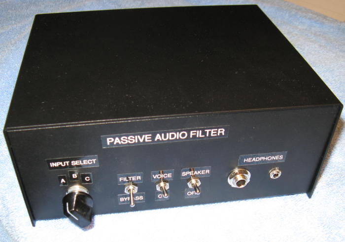
This is the completed filter unit. It contains a rotary switch to allow the
operator to select any one of three receivers without having to swap cables.
Both 1/4-inch and 3.5-mm headphone jacks are provided. An external speaker jack
is located on the rear panel along with input signal jacks.
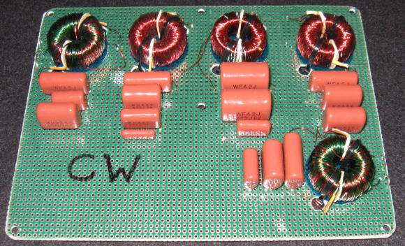
Here is the CW filter board.
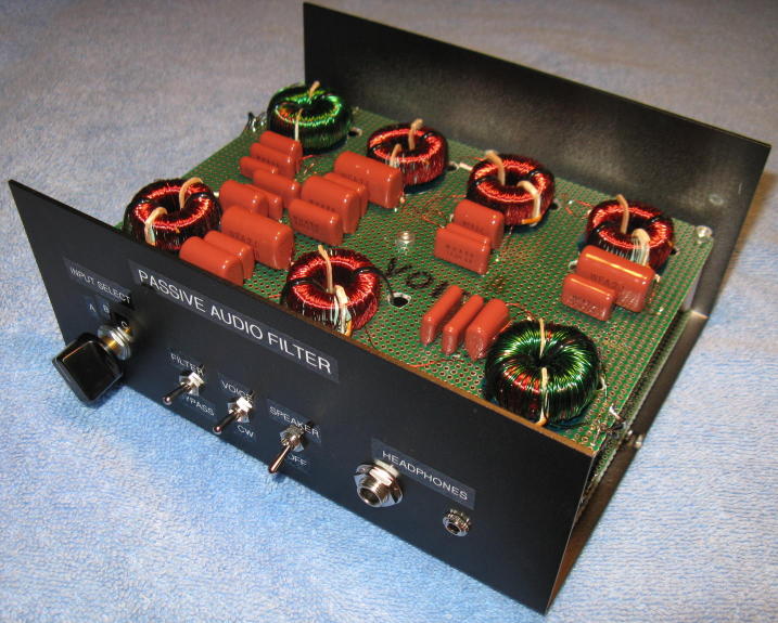
This photo shows the voice filter board installed in the enclosure. The CW
filter board is located beneath the voice filter board.
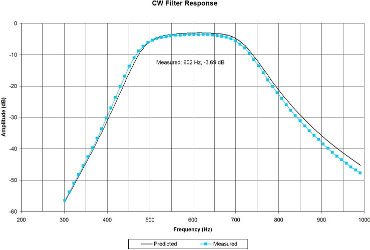
The predicted and measured CW filter responses are shown here:
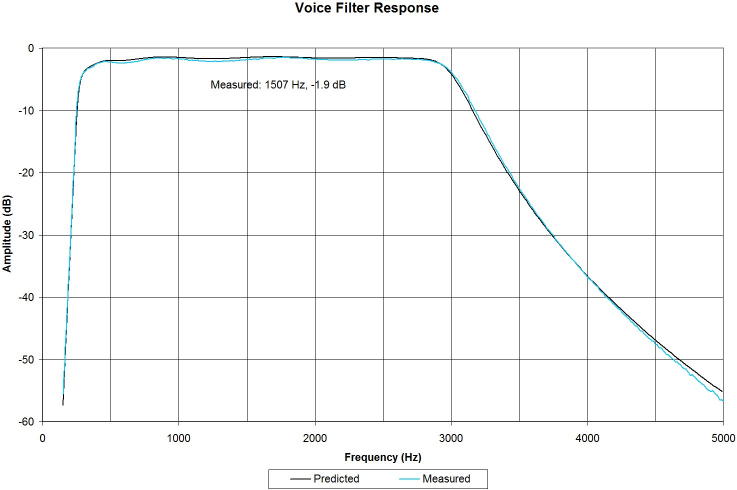
The predicted and measured voice filter responses are shown here:
The files linked below can be downloaded to obtain additional information.
A_Passive_LC_Audio_Filter.pdf
The project's history, design, construction, alignment, and testing are
described in detail in this writeup. The file size is approximately 2 Mb.
AudioFilter.xls Spreadsheet used to design the
filters and adjust the inductors.
CwSimulation.asc LTSpice schematic file used to
simulate the CW filter.
VoiceSimulation.asc LTSpice schematic file
used to simulate the voice filter.