As the design came together and shortly thereafter I corresponded by mail with several members of the amateur radio community. Selected excerpts from my own writings during this information exchange are quoted below.
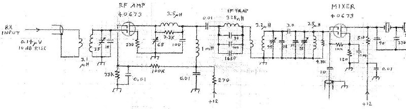
Receiver RF Amplifier and Mixer
"I found during breaboard testing that an RF amp on 20 meters was needed at times when the band is marginal... I was often able to work stations that were weak enough that copy would have been very difficult or not possible without the RF amp."
"Following the RF amp is a trap tuned to the 6.551 MHz IF. It was designed-in as a preventive measure and possibly could have been eliminated. IF rejection has never been a problem, especially given the oddball IF chosen - little or no shortwave broadcast station activity is on that freq. Such was not the case with the 6.00 MHz IF originally selected (and subsequently abandoned!)."
"The mixer stage is a fairly conventional design. The 510 ohm drain resistor serves two purposes - it properly terminates the crystal ladder filter, and it limits the maximum mixer load impedance as a function of frequency ... the xtal filter can appear as a high impedance load at some freqs..."
IF Amplifier
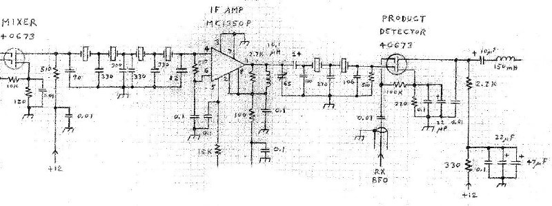
"A total of six poles of IF filtering was chosen to achieve good selectivity without letting things get too complicated. W7ZOI has written on several occasions about the desirability of having some filtering after the high gain IF stages to reduce the broadband IF noise bandwidth prior to detection. Accordingly, I placed two poles after the IF amp... the receiver is extremely quiet. Enough so that with no antenna connected, several users (myself included) have wondered if it were broken!"
"The crystal ladder filter sections were designed in accordance with W7ZOI's classic May 1982 QST article. I ordered ten 6.5536 MHz microprocessor clock crystals from Digikey and selected the six most closely matched ones from the lot. Note that although the crystal oscillation frequency was specified as 6.5536 MHz, the series resonant frequency of the crystals measured somewhat lower."
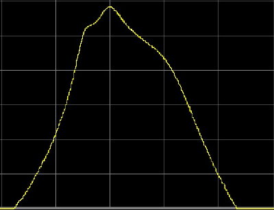
The overall IF frequency response was measured in 2014 and is shown below.
The graph scales are 500 Hz per horizontal division and 10 dB per vertical
division. The response peak is located at 6.551175 MHz.
AGC and Audio Stages
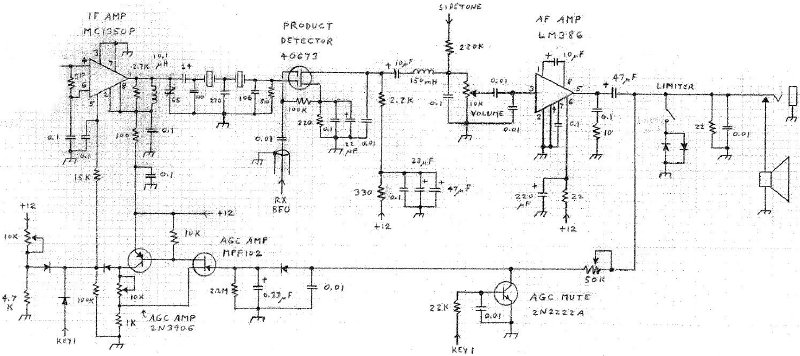
"I used audio-derived AGC as described in K1BQT's April 1983 QST article and 'Solid State Design for the Radio Amateur.' If I were doing it all over again, I would still use audio-derived AGC but I would pick it off the top of the volume control instead of the AF amp output. Then the volume control setting would have little effect upon overall AGC action. On the downside, taking AGC from the volume control would probably require addition of an AGC amplifier stage. The diode limiter across the speaker output is a last minute compromise to protect my ears when using headphones and tuning across extremely strong stations..."
"The speaker is a small 1.5 inch square type from Mouser."
VFO
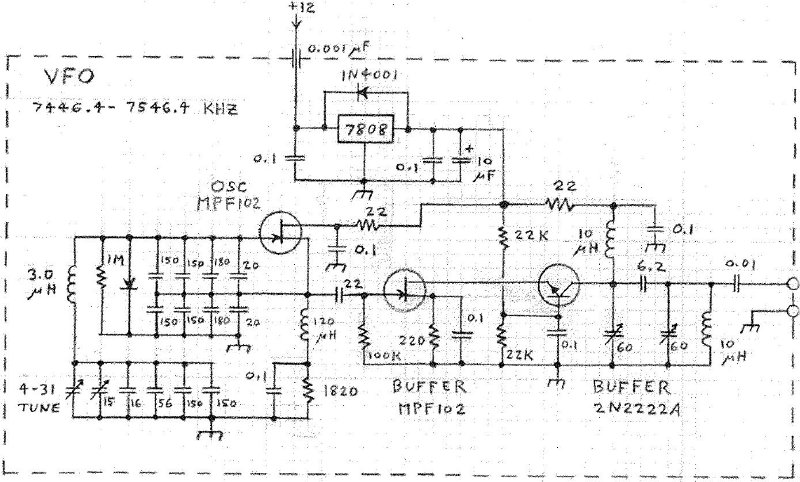
"The VFO is built in a shielded enclosure fabricated from double-sided PC board stock. Tuning is very linear with no drift, chirp, jumping or other instabilities. An inexpensive 0-100 vernier dial drives the VFO tuning capacitor, and as the rig tunes the lower 100 KHz of the band the frequency can be read directly off the vernier dial."
"... the oscillator was built using point-to-point wiring above the ground plane and the buffer was built on a small etched circuit board within the enclosure... The VFO coil was wound on a ceramic form with an air core."
BFO
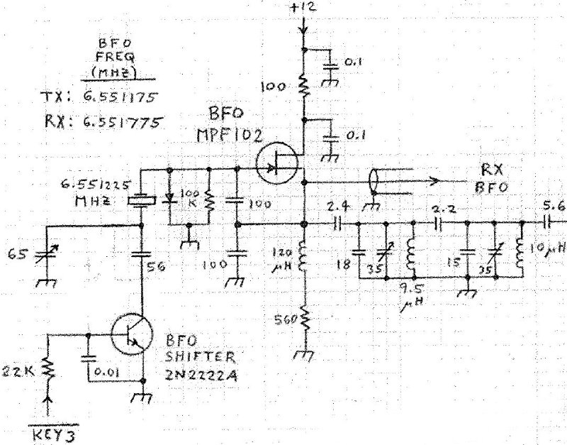
"It was necessary to order a custom BFO crystal to match the IF filter response as the Digikey crystals did not have sufficient oscillator warp range."
"The BFO frequency is shifted slightly when switching between receive and transmit. One minor side effect with the freq shifting scheme shown is a popping sound made in the receiver during keying... the amplitude of the BFO output changes... a step change... is coupled into the product detector, amplified, and makes its way to the AF output... The popping sound was brought down to a tolerable level by adding the diode on the FET gate and removing a pull-up resistor from the BFO shifter transistor collector... An audio muting circuit was considered but rejected due to insufficient board space."
Transmit Mixer and Pre-Driver Amplifier
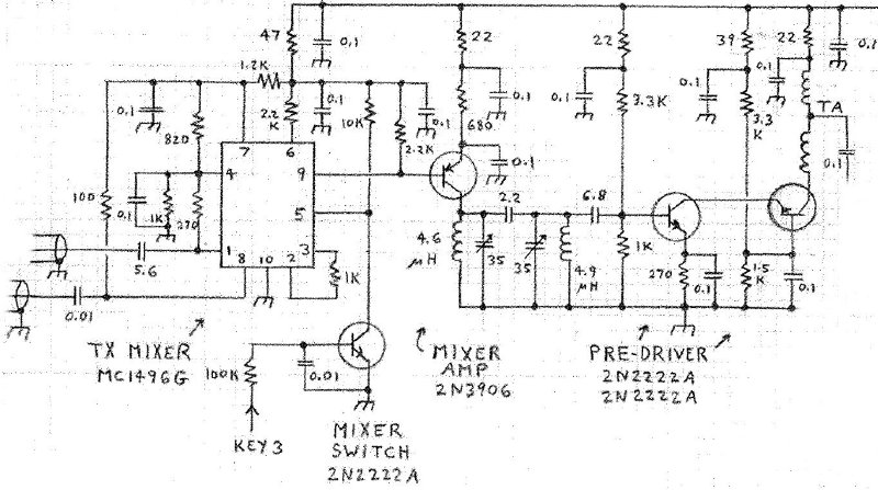
"The transmit mixer is disabled during receive by the mixer switch transistor. On transmit, the output from the mixer is amplified, filtered, and amplified further in the cascode pre-driver amplifier stage."
Transmitter Driver and Power Amplifier
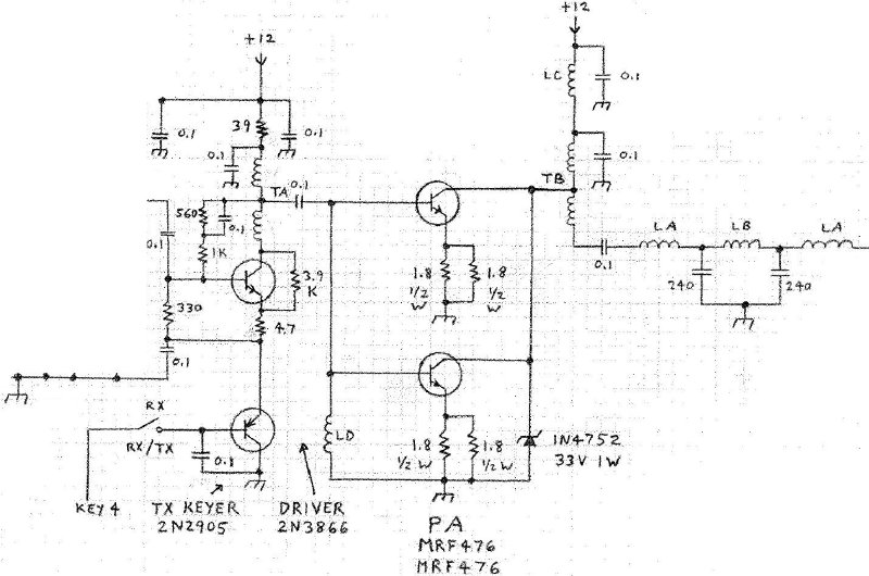

"The transmit driver and PA stages are adapted from W1FB's November 1982 QST article. One exception is the TX keying circuit, a 2N3906 and 2N2905 Darlington pair. This pair is connected as an emitter follower stage. As the rig is keyed, the 0.047 capacitor on the 2N3906 base is charged and discharged, which causes the 2N3906 base voltage to rise and fall over a period of a few milliseconds. Since the 2N2905 emitter voltage tracks the 2N3906 base voltage, the driver stage builds to and decays from full output amplitude over a period of a few milliseconds. Hence, the output signal is free from key clicks..."
Keyer and Timing Control
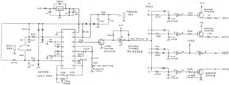
The Curtis 8044 keyer IC was very popular when the rig was built but is now obsolete.
"The 470K pull-up resistors were added to the Auto Key jack after Field Day. We were operating on a mountain top on the Appalachian Trail and a rainstorm started. Whenever a water droplet landed on the keyer paddle contacts the rig would go berserk and send code at random!"
References
1. Hayward and DeMaw, Solid State Design for the Radio Amateur, 1977.
2. Hayward, "A Unified Approach to the Design of Crystal Ladder
Filters," QST, May 1982, pp 21-27.
3. Littlefield, "Construct an Audio Amplifier with AGC for Your Simple
Receiver," QST, April 1983, pp 28-31.
4. Demaw, "The 8P6 Special - 'Hamcation' Backup Rig," QST, November
1982, pp 17-21.