Two major types of ignition systems were used on the CX and GL bikes, the CDI (capacitive discharge ignition) and the TI (or TAI, transistorized ignition). CDI's were used on CX models through 1981. Starting in 1982, CX bikes used the TI. All GL models used the TI. Of the two types, the TI is much more reliable in addition to having other advantages.
The above information is specific to US models. There may be variations for other countries.
TI Systems
Introduction
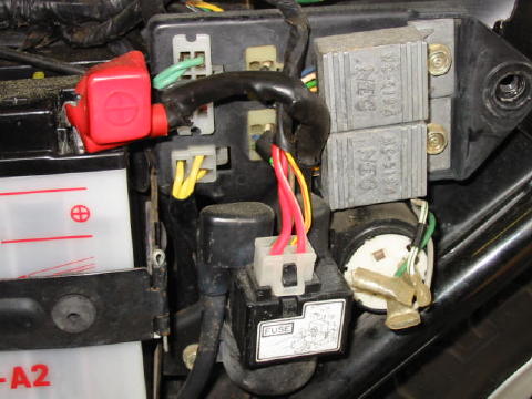
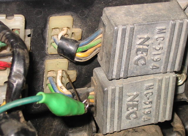
The TI system is extremely reliable. Its major components include two
ignition modules, the ignition switch, the kill switch, a timing pickup coil
assembly located at the rear of the crankshaft, and two ignition coils/plug
wires/spark plugs. The two grey-colored ignition modules are shown in this
photo.
The left and right side ignition systems are almost completely independent. The only circuits they share are power and ground.
Due to the simplicity of this system, there is not much to check. To troubleshoot a TI ignition system, proceed as follows.
Power and Ground Tests
Set the multimeter to measure DC Volts. The negative meter lead should be connected to the negative battery terminal. Turn the ignition switch to the on position.
Measure the voltage on the positive battery terminal. If it is not at least 11 Volts the battery is likely discharged or defective, and this should be corrected before proceeding further. The TI ignition system cannot operate reliably with insufficient battery voltage or with the battery disconnected. (Never try to operate the bike without a battery installed!)
Measure the voltage on the green wire at either of the ignition module connectors. The green wire is the wiring harness ground.
If the green wire reads more than a few tenths of a Volt then there is a ground problem with the wire harness. Refer to the main fuse and grounding page.
Next, measure the voltage on the black/white wire at either of the ignition module connectors. This is the power feed to the ignition modules. If the voltage here is not approximately the same as the battery voltage, the likely culprit is the kill switch or the ignition switch or the main fuse. With the multimeter settings and negative meter lead unchanged, you can now probe these items to see where the power is being lost.
Repeat the measurements while cranking the engine. If the readings in this section are all good there is no problem with the power being applied to the ignition system; the battery, kill switch, ignition switch, and associated wiring are not the problem.
Ignition Pickup Simulation Test
Once the power and grounds have been verified to be good, the test described in this section should be performed to determine if the problem is related to the ignition pickup circuit or elsewhere.
First, unplug the ignition pickup coil connector.
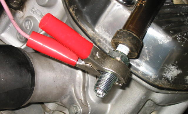
Remove the spark plug on the side that has the problem. Insert the plug into
the plug cap and ground the plug body. In this photo, the other end of the test
lead is connected to a ground lug on the frame. Do not use the valve covers for
a ground as they are insulated by rubber. Position the plug so the gap can be
easily seen.
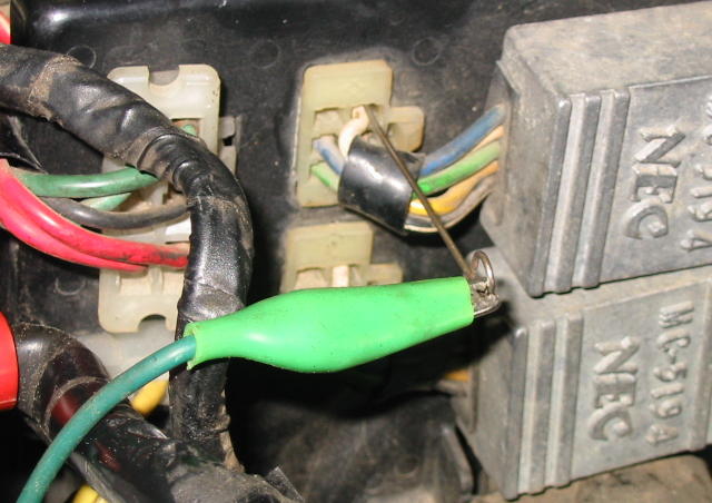
Next, probe the white wire connector pin of the ignition module associated
with spark plug under test. A short piece of welding wire works well for this.
Use a test lead or wire to make this connection.
Which module is associated with a particular spark plug? It's not safe to assume one because someone may have previously swapped the wiring harness connectors behind the panel. Accordingly, it's best to repeat this test using each module.
Set the ignition switch to the on position and repeatedly touch the other
end of the test lead to the negative battery terminal.
A spark should be created every time the test ground connection is broken.
This test simulates a pulse from the ignition timing pickup coils. If a spark is created, the problem is due to the ignition timing pick up coils or the mechanical timing advance unit, both located on the rear of the engine under the timing cover. If a spark was not created, the problem is due to something else.
Unfortunately, it is necessary to pull or move the engine forward to provide the clearance needed to remove the timing cover should that be necessary.
Timing Pickup Coil Resistance Tests
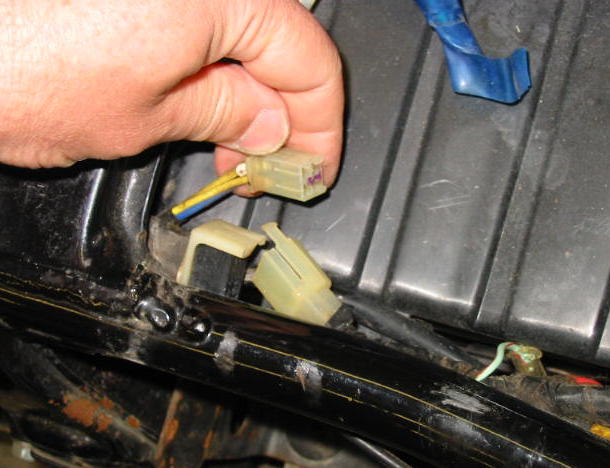
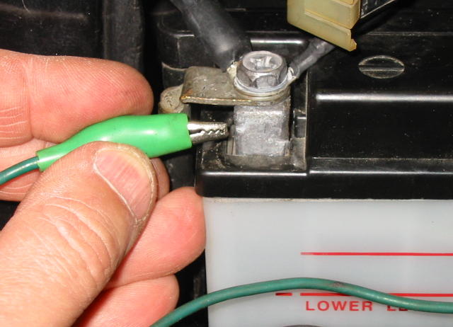
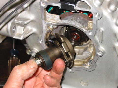
The timing pickup coils can be tested without removing the engine. There are
two coils, one for each side, and they share a four pin connector located under
the rider's seat:
Unplug the timing pickup coil connector to make the resistance measurements. Make measurements on the end of the cable that goes to the engine, not the ignition units. The end to measure is the one being held in the above photo.
The resistance between the two yellow wires should measure 530 Ohms. The resistance between the two blue wires should measure 530 Ohms. If the measured values are within ten percent of 530 Ohms that is acceptable.
Also measure the resistance between these wires and ground. The measured value should be infinity, or an open circuit.
If the pickup coil resistances check out ok, it is fairly certain the pickup coils are not faulted.
Ignition Timing and the Mechanical Advance Timing Unit (ATU)
In this section, some of the common ignition timing and associated mechanical advance timing unit problems are discussed.
The ignition timing is set during engine assembly and is not a routine maintenance action. The GL factory service manual details the static timing adjustment procedure and should be carefully followed whenever the engine is reassembled.
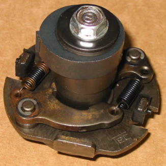
The mechanical advance timing unit is shown in this photo. It is mounted to
the rear of the crankshaft flywheel/rotor.
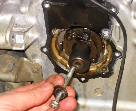
The mechanical advance timing unit is held in place with the bolt and washer as shown above. Mistakes commonly made during engine reassembly are not using the washer or not torquing the bolt to spec using a torque wrench. If the bolt is not torqued to spec it can work loose after the engine has been running for a while. Similar problems can result if the washer is omitted, as described below.
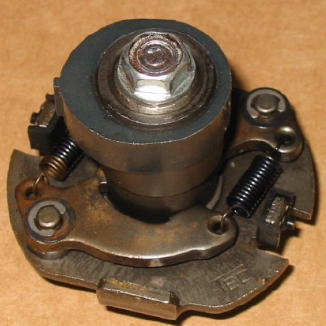
The mechanical advance timing unit consists of two major subassemblies:
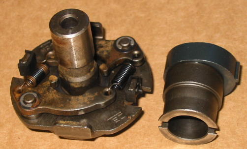
Note the washer diameter is significantly larger than the bolt head:
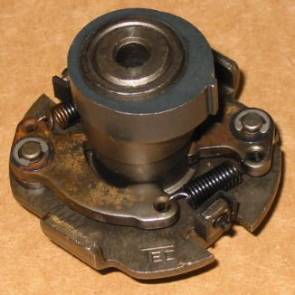
If the washer is omitted, or a smaller washer is used, the end of the
mechanism is only partially covered:
If assembled in this condition, the mechanism can come apart after the
engine has been running for some time:

When this happens, the symptom is no spark on either side. This illustrates the importance of using the correct washer during reassembly, and torquing the bolt to spec.
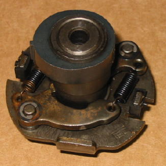
The mechanism can also come apart during handling. There are two ways it can
be reassembled. One way is correct, and the other way will result in the timing
being out by 180 degrees:
Which way is correct? My preference is to simply assume one and make absolutely certain the static ignition timing checks described in the factory service manual are performed. If the wrong way was chosen, the error will be detected at that point while it is still easy to correct. The worst thing to do is simply reassemble the engine and skip the static timing checks - more than one person has had to pull the engine to change the assembly orientation after guessing wrong. Feeling lucky?
This is the rear of the mechanical advance timing unit. Note locating pin:
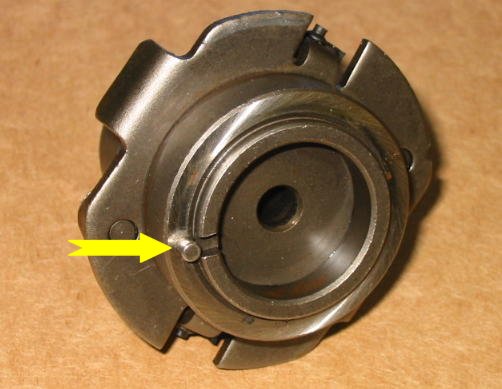
There are two slots that this pin can fit into on the flywheel/rotor, a wide
slot and a narrow slot. It should be inserted in the narrow slot:
The factory service manual procedure calls for the pickup coil static timing
to be adjusted and then checked twice, once when the crankshaft is set to
"FS" on the left side and once when set to "FS" on the
right side. When this is done, the nub on the rotor should align with the nub
on the applicable pickup coil. If the mechanical advance timing unit is
assembled or installed incorrectly the static timing will not even be close.

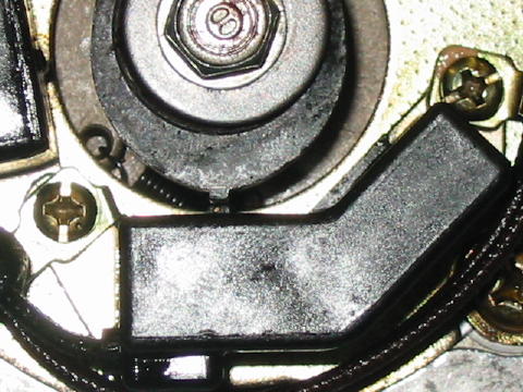
This may all sound confusing but it's really very simple and fast to check the proper orientation. One of the forum members on the Honda CX500 and GL500 Forum, fastpakr, summed it up with these words: "To test that the rotor's properly installed on the timing advance mechanism, just rotate the crank until the FS||FI marks are visible through the inspection port. If the rotor is pointing at one of the pulse generators, you're all set. If not, remove the rotor and reinstall it 180 degrees off. Verify that it's now pointing at an advance unit and you're all set."
As mentioned above, the mechanical advance timing unit is mounted to the
rear of the crankshaft flywheel/rotor. Thus, if the flywheel is not in the
proper position the timing will not be correct. The flywheel is held in the
proper position by a woodruff key on the crankshaft:
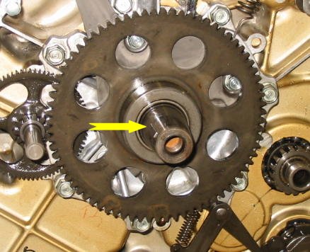
The timing may be off if this key was omitted during engine reassembly. There have also been rare instances where this key has been sheared in half.
CDI Systems
The CDI system is completely powered from the stator and is electrically isolated from the rest of the bike's electrical system. Its major components include the stator, the CDI unit, the ignition switch, the kill switch, two pickup coils, and two ignition coils/plug wires/spark plugs.
Since the system is completely powered from the stator, if the engine turns over too slowly there will be insufficient electrical power generated in the stator to support ignition. Therefore the ignition system could appear to be malfunctioning when in reality the problem is nothing more than a weak battery. If the engine does not turn over fast it would be worth jumping the battery to see if the bike starts - see the comments on jump starting on the battery charging page.
The CDI unit has a black wire with white stripe attached to an inline bullet connector. This wire is an input to the CDI unit, and its purpose is to turn off the ignition. Grounding this wire will kill the ignition. If this connector is unplugged, the bike will continue to run even if the ignition switch is set to off and the kill switch is engaged.
Similarly, if there is a short to ground on this wire then the ignition will not operate. The inline bullet connector can be used for troubleshooting. If the bike will not start, unplug the bullet connector and try again. If it starts this time, the problem is likely either the kill switch, the ignition switch, or the associated wiring. Troubleshooting techniques associated with finding a short to ground can then be used to isolate the problem.
CDI unit failures and stator failures are both fairly common. Unfortunately, the CDI unit cannot be tested with a multimeter so the process of determining if a CDI unit is bad comes down to swapping it out with a known good unit.
Although the CDI system is electrically isolated from the rest of the bike's electrical system, it does share the same stator. Even though the stator CDI windings are electrically isolated from the charging windings, they are linked together magnetically. Consequently, a shorted charging winding can impact ignition system operation. On occasion, unplugging the stator charging connector (the one with three yellow wires) will allow the bike to be started when it could not be started otherwise. If this happens, it is virtually certain that the stator has a shorted winding and needs to be replaced.
Resistance checks can be performed on the stator with limited success. If a stator resistance measurement is grossly out of spec then the stator is virtually certain to be defective. However, if the resistance measurements are within 10 percent or so of spec limits the stator may or may not be bad. To complicate matters further, the resistance measurements could all be well within spec and the stator could still be bad. The resistance checks are outlined in the Honda factory service manual. A pdf copy can be downloaded for free from here.
The CDI stator has two windings dedicated to powering the CDI system, and the remaining windings are used by the charging system. In contrast, all of the TI stator windings are used by the charging system. Consequently, the TI stator has significantly more electrical output power for charging the battery and powering accessories such as heated clothing or auxiliary lighting.
An aftermarket replacement CDI unit has recently become available from Ignitech in the Czech Republic and has been getting great reviews. The Ignitech unit obtains its power from the bike's 12 Volt electrical system, not the stator, thus allowing the TI stator to be installed in place of the CDI stator. If you are considering an upgrade to this unit, it would be worth checking out the Honda CX500 and GL500 forum to see if a discount group purchase is currently being made.
Ignition Coils
Ignition coils have been known to fail on occasion, but they are generally pretty reliable. The most dependable method of testing a suspect ignition coil is to swap it out with another one. The left and right side coils are electrically identical, so if it has been determined that one side of the bike is not firing then the coils can be swapped to see if the problem follows the coil or stays on the same side.
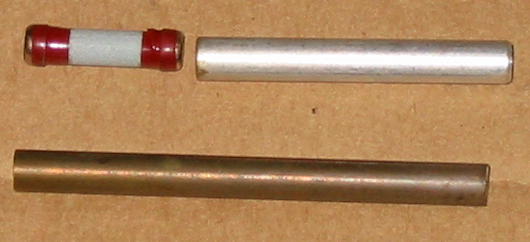
Plug Wires and Caps
Problems with spark plug wires and spark plug caps are not uncommon.
Plug cap problems usually show up as an open circuit and are often
intermittent. In some cases, the internal resistor fails. This resistor is a
holdover from the days when AM radio was prevalent. Its purpose was to reduce
AM radio interference. A popular modification is to replace the resistor and
its adjacent aluminum spacer with a piece of brass rod stock cut to length.
A plug cap problem was recently diagnosed on a GL650. The bike would start up and idle fine for about twenty minutes and then it would stumble and die. After it had cooled down, it could be started again and the cycle would repeat. The problem was isolated over a period of time by methodically swapping parts until it went away. A multimeter resistance reading showed that the plug cap had an open circuit. It was then cut open with a Dremel tool for inspection. The top contact within the cap had significant corrosion and some sort of greyish-black build-up on it.
Plug wire problems are usually associated with a breakdown in insulation, resulting in arcing. Start the engine when it is completely dark and look along the wire for evidence of arcing. You can also run a small neon test bulb alongside the wire to see if it fires. A hand can also be used, but it will be more painful when an insulation breakdown is found.
Spark Plugs
Defective brand new spark plugs due to manufacturing errors are sometimes encountered. In one instance the center electrode inside the plug was completely missing. If an ignition problem arose during maintenance when the plugs were replaced, try re-installing the old ones. If one new plug is defective there is a good chance the other one is also bad, particularly if both plugs came from the same production lot.
Parts Interchangeability
Few if any parts can be interchanged between the TI and CDI systems. The ignition coils are incompatible. The kill switches are also different - the TI kill switch creates an open circuit to stop the ignition, whereas the CDI kill switch creates a short circuit to perform the same function.
Problems When It Rains
Honda CX500 and GL500 Forum member
Yooper Ken posted this information, reproduced here with permission:
"The problem was whenever it rained my bike would simply not run as good
and go as far as to run downright crappy. But as soon as the rain quit the
problem was gone. I even blasted it with a garden hose and couldn't replicate
the problem.
After disassembling everything electrical I could think of, I was down to the coils. On the 82cx and others, the coil wires can be removed by unscrewing a plastic cap on the wire. There is a compression seal around the wire under the cap. Apparently mine didn't seal well enough. I trimmed an 8th inch off the wires, cleaned the terminals on the coil, and put a nice bead of silicone around the rubber seal. After tightening the caps/wires back on to the coils and cleaned up the excess silicone that oozed out....that was it.
I now can have ridden in the hardest down pours without issue."
Thank you for sharing this, Ken.
Multimeter Usage
Main Fuse and Grounding
Charging Problems
Ignition Problems
DC Voltage Testing
Resistance Tests
Wiring Fabrication and Repairs
Stray Topics