Revised 3-16-2012
Introduction
A number of motorcycle electrical problems have been diagnosed on the Honda CX500 and GL500 Forum over the past few years. Many of these problems have been found to be due to the same failure mechanisms. Some of the more common ones are addressed here.
This writeup is mostly directed towards the GL500/GL650 bikes because those are the ones I own and am most familiar with. However, much of the material is also applicable to the CX models. Further, the general troubleshooting techniques presented here are applicable to many motorcycles.
Multimeter Usage
It is very difficult, if not impossible, to troubleshoot electrical problems
without proper instrumentation. Without it you're essentially blind to what is
happening in a circuit. A multimeter is all that is needed for most
troubleshooting and cheap one will work fine. One can be obtained for only a
few bucks from places like
Harbor
Freight Tools. If you're at all serious about tracking down an electrical
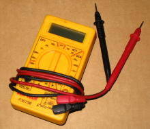
problem there is no excuse not to have a multimeter. Here is one that I use
most often.
Even a simple multimeter has a multitude of measurement capabilities and corresponding settings. But the vast majority of all problems can be accurately diagnosed using only three basic measurement types: Resistance, DC Voltage, and AC Voltage. Since multimeter usage is so important, a few minutes spent reviewing basic multimeter usage is time well spent.
Meter Lead Connections
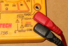
Test leads are provided with the meter. There are often several places they can
be plugged into for various measurements but usually there is one configuration
that is almost exclusively used in practice. The black (or negative) meter lead
should plugged into the jack labeled COM or COMMON or sometimes NEG, depending
upon the specific meter. The red (or positive) meter lead should be plugged
into the jack labeled V or Ohms or similar.
Often there is a separate connector labelled A or AMPS or similar (10ADC in
this example). This is intended for making high current measurements. Current
measurements will not be made in this writeup, so don't worry about its usage.
Resistance Measurements
Resistance measurements are made with the meter function switch set to
measure resistance. The measurement unit for electrical resistance is the Ohm,
often abbreviated with the Greek letter Omega or
![]() .
.
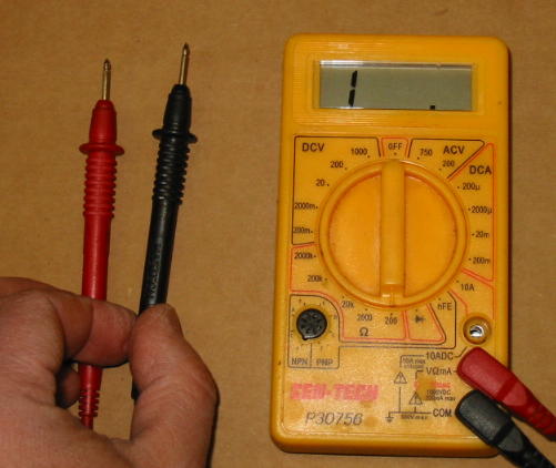
Here the meter is set up to measure resistance. Note the function switch is
pointing to 200 in the Ohms section. The Ohm function section indicates
resistance measurement, and the 200 indicates the meter will measure
resistance values ranging between zero Ohms up to a maximum of 200 Ohms. In
this example, the display shows a 1 followed by a blank display. This
means the measured resistance is in excess of 200 Ohms. With no connection
between the meter leads, an open circuit (or infinity Ohms) exists. Since
infinity is greater than 200, this reading makes sense.
To measure resistances greater than 200 Ohms, the meter function switch needs to be changed. A setting of 2000 will allow the meter to measure resistance values ranging between zero up to a maximum of 2000 Ohms.
Note the letter K in the other resistance ranges. K is an abbreviation for "kilo" in the metric system and means 1,000. So if the meter switch is set to the 200K position, it can measure resistances ranging between zero up to a maximum of 200,000 Ohms.
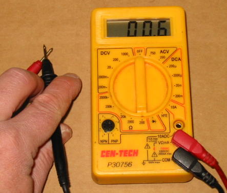
Here the meter is set to measure resistance in the range of zero to 200
Ohms. With the meter leads touched together, a short circuit (or zero Ohms)
exists between the meter leads. The meter reading indicates 0.6 Ohms. Although
this is a very small value it is certainly not zero. In practice, the meter
leads themselves have some finite resistance and this probably accounts for
most of the non-zero meter reading.
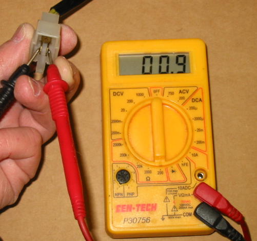
Here the resistance between two stator connector pins is being measured. The
meter reading indicates 0.9 Ohms. In reality, the true resistance is probably
closer to 0.3 Ohms because the meter leads are contributing around 0.6 Ohms to
the measurement as we just determined above.
Resistance measurements are NEVER made on a powered or live circuit. In addition to inaccurate readings, damage to the meter or the circuit itself could occur.
When making resistance measurements, be careful not to touch the meter leads. The human body is not a perfect insulator and the reading obtained could simply be your electrical resistance. Lie detector manufacturers rely on this bit of trivia.
DC Voltage Measurements
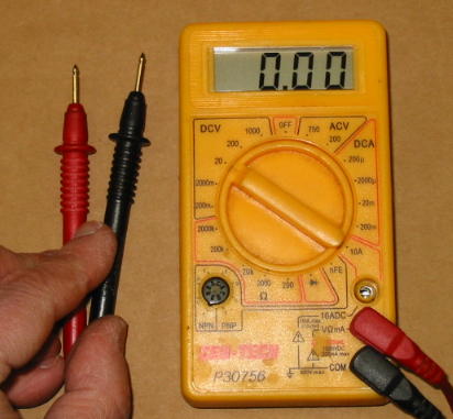
Here the meter is set to measure DC Voltage. The function switch is set to
the DCV section to measure DC Voltage, and the range position selected
is 20. In this case, the meter will measure DC Voltage in the range
between zero and 20 Volts. The meter leads are not connected to a DC voltage
source, so the meter reads zero Volts as expected.
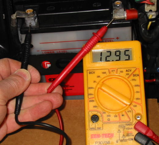
Here the meter is being used to measure battery voltage. The function switch
is set as above, the negative meter lead is touching the negative battery post,
and the positive meter lead is touching the positive battery cable terminal.
The reading is 12.95 Volts.
AC Voltage Measurements
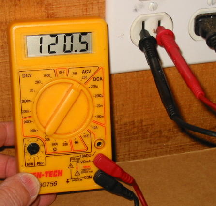
AC Voltage measurements are made in much the same manner as DC Voltage
measurements. In this example, the meter function switch is set to ACV
and the range selection is 200. Accordingly, the meter is set to make AC
Voltage measurements in the range from zero to 200 Volts. The meter indicates
that the garage AC mains voltage is 120.5 Volts.
There is no real need to be concerned with the other multimeter measurement capabilities for most general motorcycle electrical troubleshooting.
Meter Negative Lead Connection
When making most motorcycle DC Voltage measurements (and many Resistance measurements), it is common for the measurement to be "referenced to ground." Quite simply, this just means the negative lead of the meter is connected to a known good ground reference point when making the measurement. In this writeup, whenever a DC Voltage measurement is called for it should be assumed the negative meter lead is connected to ground unless specifically stated otherwise.
So what is a known good ground reference point? For a multitude of reasons,
my strong preference is the negative battery terminal.

By selecting this point, the negative meter lead is guaranteed to be connected to the most negative power source point, regardless of the condition of other ground connections on the bike. This can greatly simplify troubleshooting in the event that a faulty ground connection exists someplace.
As an aside, the valve covers should never be used as a ground connection because they are frequently insulated from the engine block.
Now that we are all experts in making the three types of commonly needed electrical measurements, we can move on to using this knowledge to diagnose faults. You can select a desired topic from the list below or go through all of them in sequence. Regardless, I strongly recommend first viewing the Main Fuse and Grounding section as failures here have a very high rate of occurrence.
Multimeter Usage
Main Fuse and Grounding
Charging Problems
Ignition Problems
DC Voltage Testing
Resistance Tests
Wiring Fabrication and Repairs
Stray Topics