Fan Always-On Modification
Introduction
Another modification recently discussed on the CX/GL Forum is to have the fan always running when the ignition is switched on. When the fan is needed, it operates normally. But when it is not needed, the fan continues to run, but at a slow speed. A resistor is connected in series with the fan when it operates at slow speed.
One benefit of this modification is a reduced surge current when the fan is switched on. Another benefit is the prevention of restricted airflow due to a non-running fan.
I have not tried this modification yet, so I have no direct experience regarding these benefits. However, details are included here should you wish to perform the modification.
Resistor Selection
The resistor value (measured in Ohms) determines how fast the fan runs; the fan will run slower as the resistance value is increased.
There is no single resistor value that is appropriate for all fans. Its value is best determined experimentally by trying different values until the desired slow fan speed is obtained.
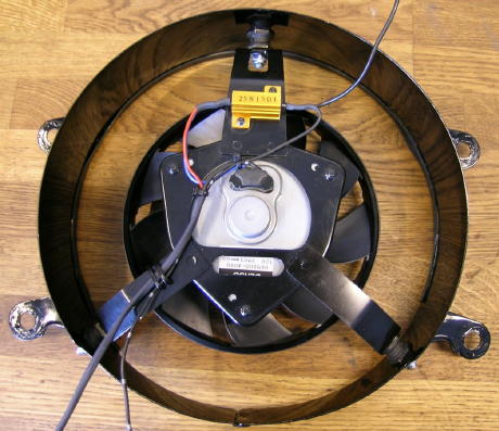
Forum member MGR1 has found a resistor value of 15 Ohms works well
with his installation, shown in this photo. The resistor is the gold-colored
device secured to the top fan bracket.
In addition to the resistor's value in Ohms, its power rating must be considered. To determine the power dissipated by the resistor, the following formula can be used:
P = V2 / R
where P is the power dissipated in Watts, V is the voltage across the resistor, and R is the resistor value in Ohms.
If a worst-case-possible voltage of 15 Volts is assumed as this is installed on a bike, the formula simplifies to
P = 225 / R
In this example, if a 15 Ohm resistor is used then its worst-case power dissipation is P = 225 / 15, or 15 Watts. MGR1 used a 25 Watt resistor, so his selection has a significant safety margin.
Even though the resistor has a sufficient power rating, it may still get rather warm. Confined spaces such as under the seat may be a poor choice for the resistor mounting location. MGR1's selected location has plenty of airflow and is a good choice.
Resistor Connections
The resistor should be wired across the contacts used to interrupt the current to the fan when it is switched off.
If the fan power relay modification has been performed, the resisistor should be connected across relay terminals 30 and 87.
If the fan power relay modification has not been performed, the resistor should be connected across the radiator thermal switch terminals.
Electric Fan Conversion Justification 500
only
Tachometer Cable Screw Replacement 500 and 650
Electric Fan Selection and Mounting 500 only
Camshaft Clearance Considerations 500 only
Fan Power Relay 500 and 650
500 Radiator Temperature Switch 500 only
650 Radiator Temperature Switch 650 only
Fan Always-On Modification 500 and 650