Fan Power Relay
Based on personal observations and posts on the CX/GL Forum, ignition switch failures are relatively rare for 500's but not uncommon for 650's. Further, inspection of a handful of 650 ignition switches revealed they all had evidence of overheating and arcing of the contacts.
The electrical loads of TI ignition 500 and 650 bikes are essentially the same except for the extra fan current of the 650's. In my opinion, this extra load is a major contibutor to 650 ignition switch failures. Accordingly, it is not unreasonable to expect similar problems with 500 ignition switches some time after conversion is made to an electric fan.
An obvious solution to the problem is to use a relay to switch the fan power. If this is done, the relatively high current associated with the fan itself would not pass through the ignition switch or the radiator temperature switch. The only additional current passing through the either of these switches is that needed to operate the relay coil.
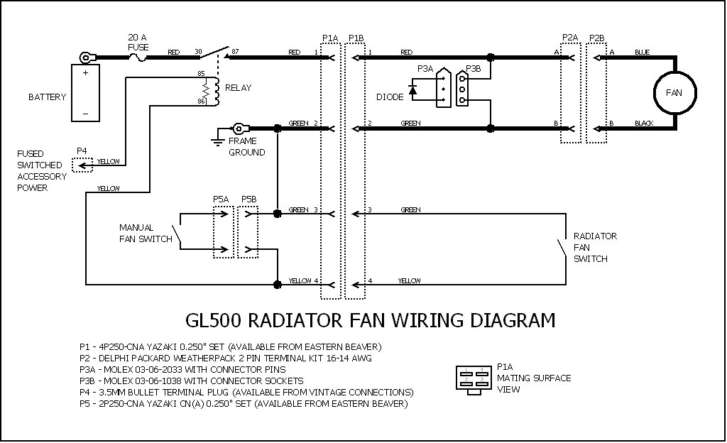
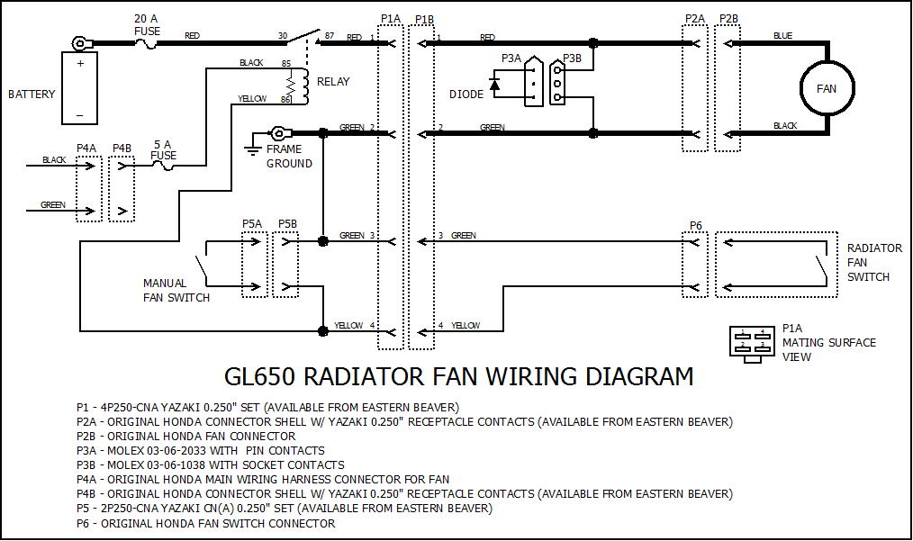
The following two diagrams show the fan relay wiring for my GL500 and GL650
bikes. Note the close similarities between them.
The wires denoted by heavy lines are 16 AWG, and the other wires are 18 AWG.
The 20 Amp fuse is an automotive blade type fuse installed at the battery positive terminal. The fuse provides protection in the event of a severe overload or short to ground. Although not shown on the diagram, this fuse also feeds a high current accessory connector that can be used to power an air compressor or other external devices from the battery.
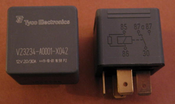
Almost any automotive power relay could have been used, but I selected a
relay that has an internal resistor connected across the coil. The risk of
"tack-welding" the contacts is significantly reduced when a resistor
is used for transient suppression, as is described in
this TE Connectivity
application note. My relay choice was the Tyco V23234-A0001-X042, sold by
Waytek as item number
75414.
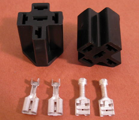
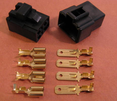
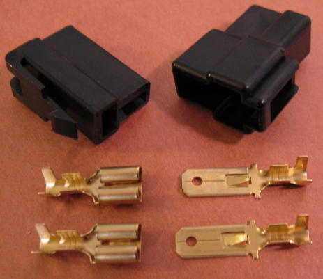
To make connections to the relay, a relay connector housing and contact
terminals were used. These are Waytek item numbers
75281
and
31073,
respectively.
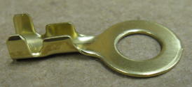
The frame ground terminal is the Eastern Beaver
BLA-106
6mm brass ring terminal.
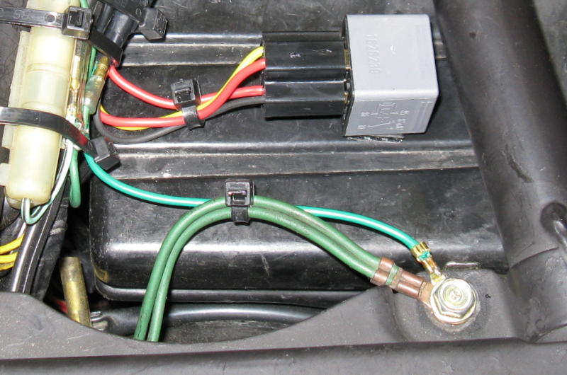
The relay was secured to the top of the airbox under the seat with industrial
strength adhesive-backed Velcro. For good adhesion, both surfaces were cleaned
with alcohol prior to installation. The ring ground terminal is visible in the
lower right corner.
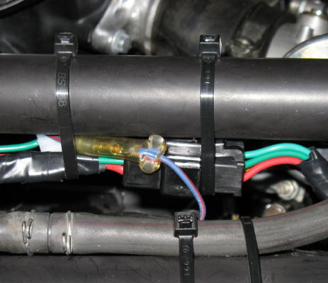
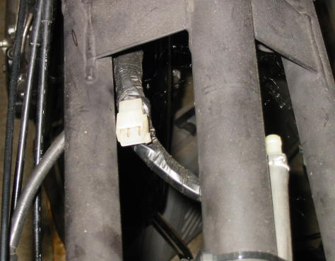
Connector P1 is the Yazaki 0.250 inch
4P250-CNA
set from Eastern Beaver.
P1 provides for radiator and fan removal without the need to cut any wires.
It was installed under the fuel tank, in front of the carburetors, on the right
side.
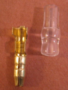
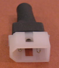
For the 500, relay power was obtained from the accessory power connector
located under the seat. This connector is fused at 5 Amps.
An SB2
3.5mm brass bullet terminal from Vintage Connections fits the accessory power
connector perfectly.
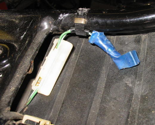
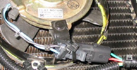
For the 650, relay power was obtained from the connector in the main wiring
harness that orignally powered the fan. This connector is only fused by the
bike's main fuse, so a 5 Amp automotive blade fuse was added here (not shown.)
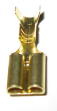
The mating connector shell from the original 650 radiator wire sub-harness
was re-used. A new
Yazaki
0.250 inch receptacle terminal from Eastern Beaver was installed in the
connector shell.
Connector P5 is the Yazaki 0.250 inch
2P250-CNA
set from Eastern Beaver. It is used for connection to an optional switch to
manually force the fan power on.
I chose not to install a manual switch at this time. However, connector half P5B was installed to make it easy to add a manual switch at a later date, if desired. It was installed under the fuel tank, in front of the carburetors, on the left side.
A Snubber Diode was
included to reduce voltage spikes that can result when the fan power is
abruptly removed. I selected a
1N5819
Schottky diode from Digikey, although many other rectifier diodes will work
fine, including the 1N540x series from Radio Shack. The diode was mounted to a
Molex
03-06-2033
connector shell with
02-06-2103-C
pin contacts, also from Digikey, and then covered with heat shrink tubing. The
mating connector is a Molex
03-06-1038
with
02-06-1103-C
socket contacts. This assembly was mounted adjacent to P1 under the fuel tank,
as this location provides some protection from the elements.
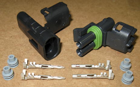
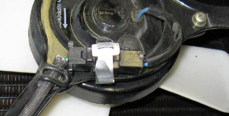
For the 500 fan conversion, a
Delphi
Packard Weatherpack connector was installed on the Ducati fan wire leads at
P2.
For connection to the 650 fan at P2, the original mating connector shell was
re-used with new
Yazaki
0.250 inch receptacle terminals installed.
Connections to the radiator temperature switch are discussed in the applicable Radiator Temperature Switch section.
Electric Fan Conversion Justification 500
only
Tachometer Cable Screw Replacement 500 and 650
Electric Fan Selection and Mounting 500 only
Camshaft Clearance Considerations 500 only
Fan Power Relay 500 and 650
500 Radiator Temperature Switch 500 only
650 Radiator Temperature Switch 650 only
Fan Always-On Modification 500 and 650