650 Radiator Temperature Switch
The 500's and the 650's use the same thermostat. So if the engine coolant temperature is being regulated by the thermostat then it makes sense that both bikes would have similar temperature gauge readings.
In fact, this is the case when riding a 650 at speeds where there is plenty of airflow through the radiator. The temperature gauge typically remains just sightly to the right of mid-scale. The measured temperature is being held relatively constant by the thermostat as the 650's fan is not operating at all. Since cruising down the road is the bike's normal operating mode, if designed properly the engine should be operating at its optimum temperature.
With insufficient airflow the temperature gauge display creeps upward and the fan eventually turns on. This happens somewhere around 3/4 to 7/8 of full scale, higher than most folks are comfortable with. Most likely the thermostat is wide open in this situation and is having no effect upon engine coolant temperature regulation. The system is running "open loop" as far as the thermostat is concerned.
Lowering the temperature at which the fan turns on lowers the coolant temperature in the radiator. The goal is to lower the coolant temperature to the point where it is within a range that the thermostat can regulate. This can be accomplished by replacing the radiator temperature switch with one that turns on at a lower temperature.
From
this
post on the VFRWorld forum, the following switches have a lower temperature
range than the original Honda temperature switch, closing at 88.5C to 91.5C and
opening at 82C to 88C:
Beck Arnley 201-0817
Borg Warner TFS500
Echlin
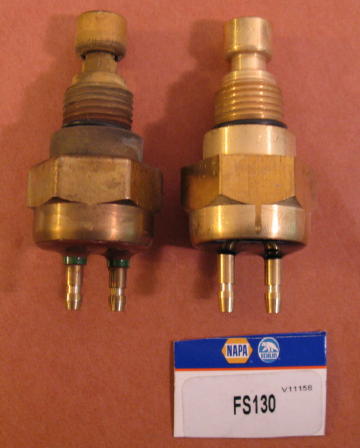
FS-130 (NAPA Auto Parts)
Four Seasons 35934
Gates T274
Niehof WA-639B
Wells SW504
Good results have been reported with the Echlin FS-130 and the Borg Warner TFS500. Performance results of the other listed switches in a CX/GL application have not been verified to my knowledge, although they are also likely to be fine.
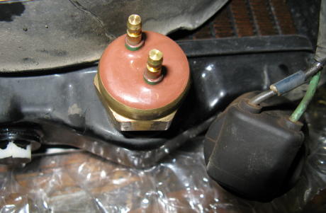
Replacing the 650 radiator thermal switch is a simple operation. First, the
connector is unplugged from the switch.
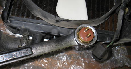
Next, the switch is removed from the radiator. Caution - the lower
radiator tank can be easily bent, particularly if a lever action is used to
break the switch loose. Use of a wrench as shown in this photo is not a good
idea.
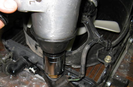
The risk of damage to the radiator tank is much lower if an impact wrench or
similar tool is used to remove the switch, as the applied force is purely
rotational.
The original Honda switch and the Echlin replacement are compared
side-by-side.
The replacement switch has been installed.
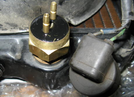
This is only applicable if a fan power relay is being installed: The original mating fan temperature switch connector, shown in the above photo, is referred to as P6 on the fan power relay wiring diagram. The connector wires were cut and spliced with longer wires to reach the P1B connector half.
Electric Fan Conversion Justification 500
only
Tachometer Cable Screw Replacement 500 and 650
Electric Fan Selection and Mounting 500 only
Camshaft Clearance Considerations 500 only
Fan Power Relay 500 and 650
500 Radiator Temperature Switch 500 only
650 Radiator Temperature Switch 650 only
Fan Always-On Modification 500 and 650